Inspection of a Complex Headlight
Car headlights aren’t as simple as they appear to be. There is a lot of engineering involved in their manufacturing. This is so that they result in nice looks as well as attain the required light handling and reflection properties. Since the light flashed from a car’s headlights has to illuminate far away objects in the path of the car, there is extensive testing done on the light reflection properties of the headlight.
The headlight consists of an injection molded part which adds to the problem of producing an accurate final part. This is due to the inherent shrinkages and other variables in the molding process. So this means the mold has to be near perfect and conform with the design intent within the required tolerances. Initially, the mold is dimensionally inspected, and tolerances of two thousandths of an inch are used to decide if the mold is usable or not. Conventional CMM machines do not generate enough measurement points to provide a complete picture of the whole mold. So, they are generally measured by optical scanning systems.
Applications 3D was called in to do such an inspection on an automotive headlight optics mold insert. Since the project was “hot”, the measurement had to be completed on the weekend at the customer site. The measurement was to be done with a white light scanner with the highest accuracy and resolution. So, the complete mold was scanned with no reflective area of the mold remaining unmeasured.
The Process
The measurement was to be done with a white light scanner with the highest accuracy and resolution. So, the complete mold was scanned with no reflective area of the mold remaining unmeasured. This was achieved using the state-of-the-art Steinbichler Comet 75 scanning system. This system consistently achieves accuracies of less than one-thousandths of an inch for each measurement. Since this system uses white light as a modus operandi, the mold insert was coated with a micro-thin layer of reflective material. However, this material is not damaging to the part and can be wiped off with a cloth. The scan was completed on time, resulting in millions of points on the surface of the mold.
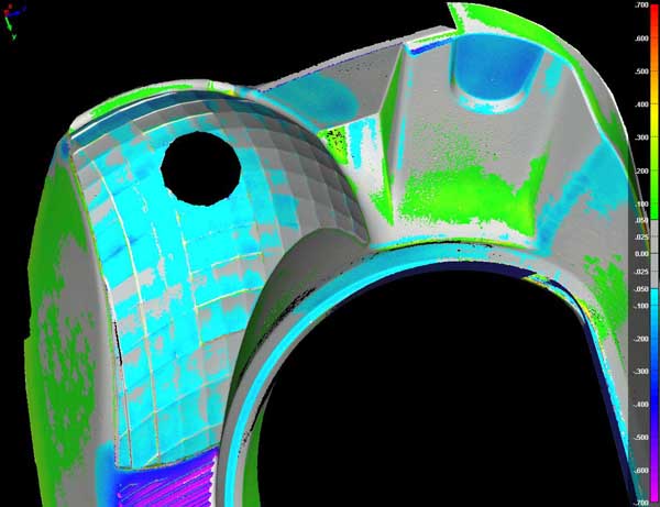
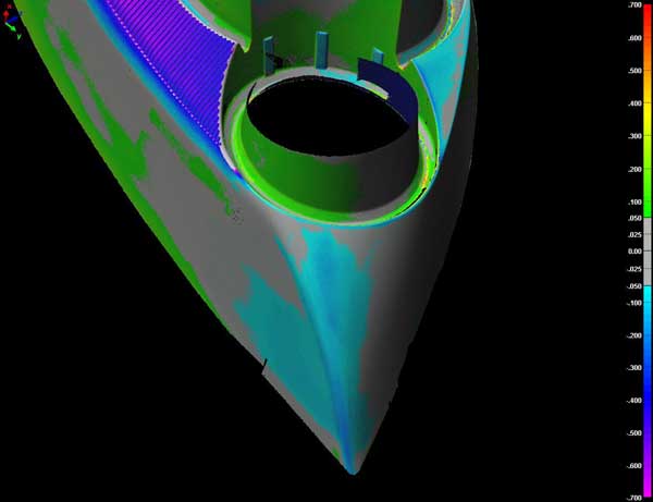
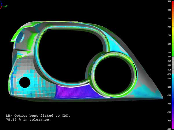
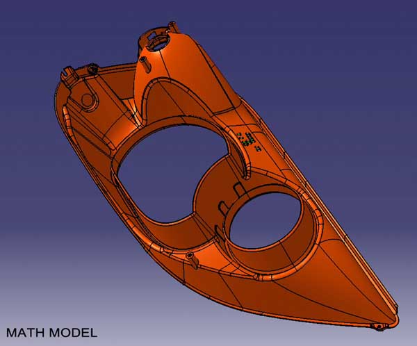
This scan data was then compared with the original CAD file of the mold, the same file which was used to manufacture the mold. Finally, the inspection results were provided to the customer in the form of easy-to-read color plots. The plots represented each area on the mold with a different color based on how much it was out of tolerance. The in- tolerance areas were shaded grey for easy identification. As well, old-fashioned, text reports were also generated for those familiar with CMM-type reports. The mold insert was found to be significantly different than the CAD data (or the math data), thus requiring extensive modifications to the mold to conform to the required tolerances.