GM Needs a Refresh
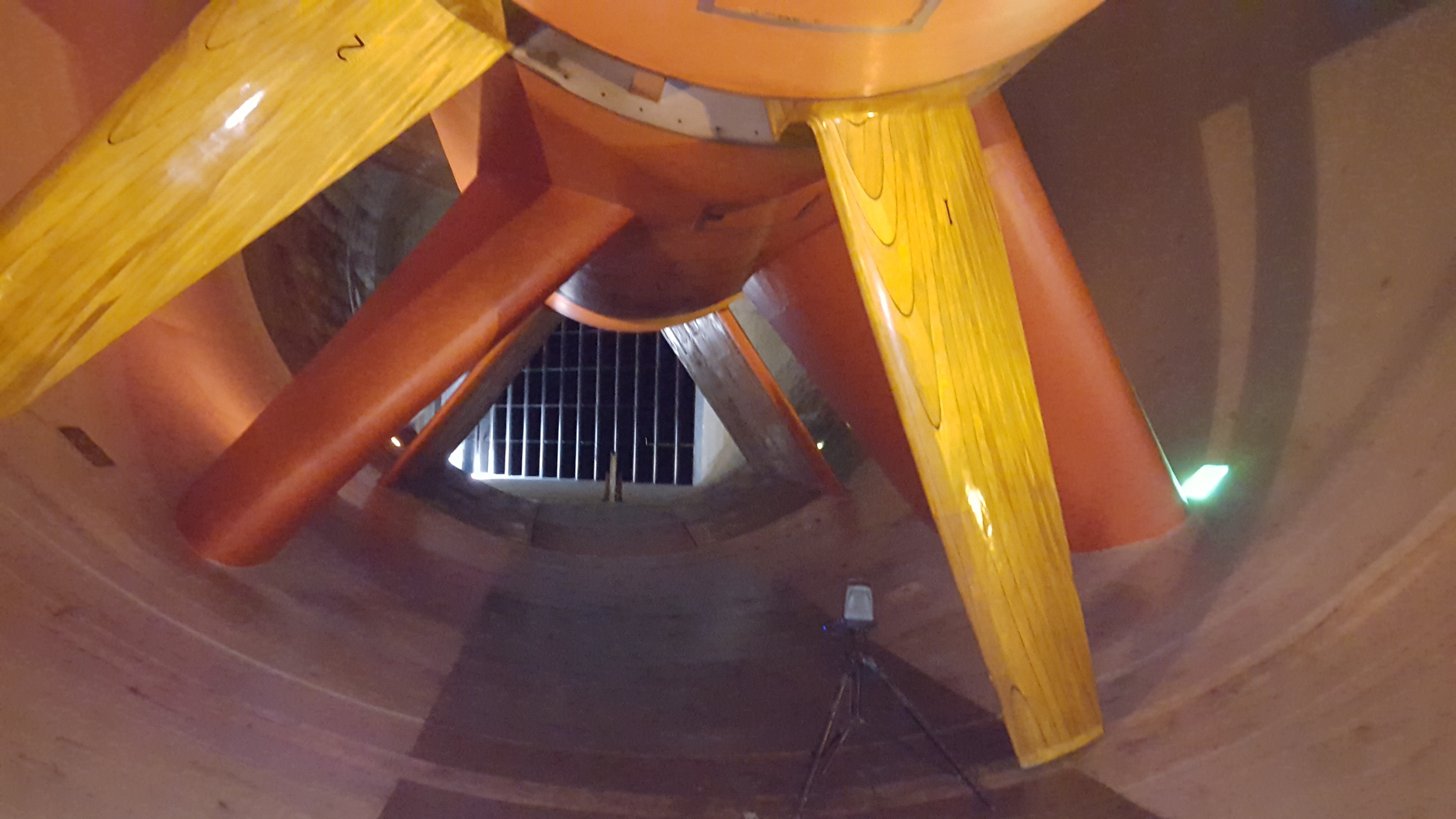
More than 40 years ago the General Motors wind tunnel began testing the aerodynamics of all its vehicles. For this purpose, a large full-scale wind tunnel was built. At the heart of this wind tunnel is the massive turbine wheel with 5 blades turning at high speed. Each blade is more than 220 inches long and is crafted to be relatively lightweight. However, due to the size of the blade, they still weigh about 1 ton each.
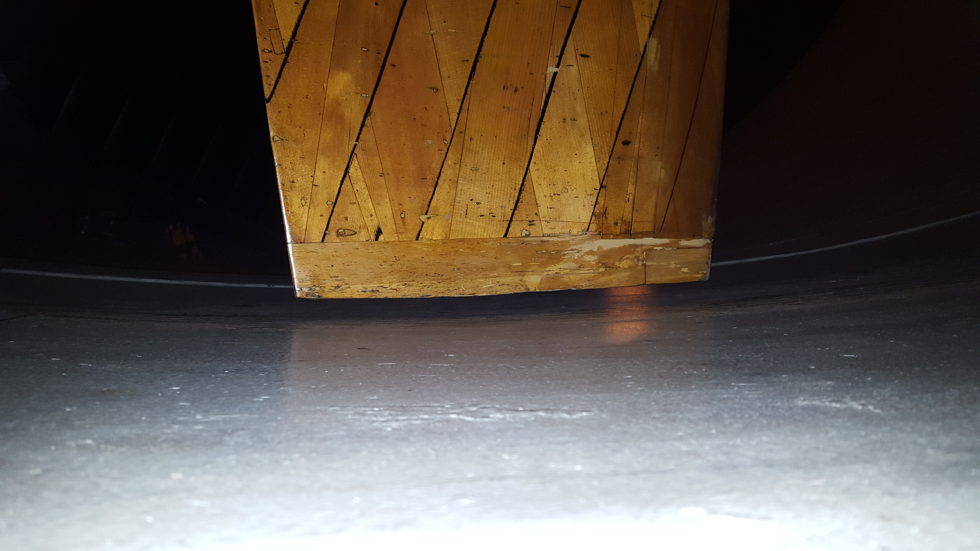
During the course of usage over the last 40 years, the tips of the blades were wearing off, and the engineers were also worried about the structural integrity of the wooden structures. This led them to the decision to have these blades fully 3D scanned and reverse engineered so that they could be replicated.
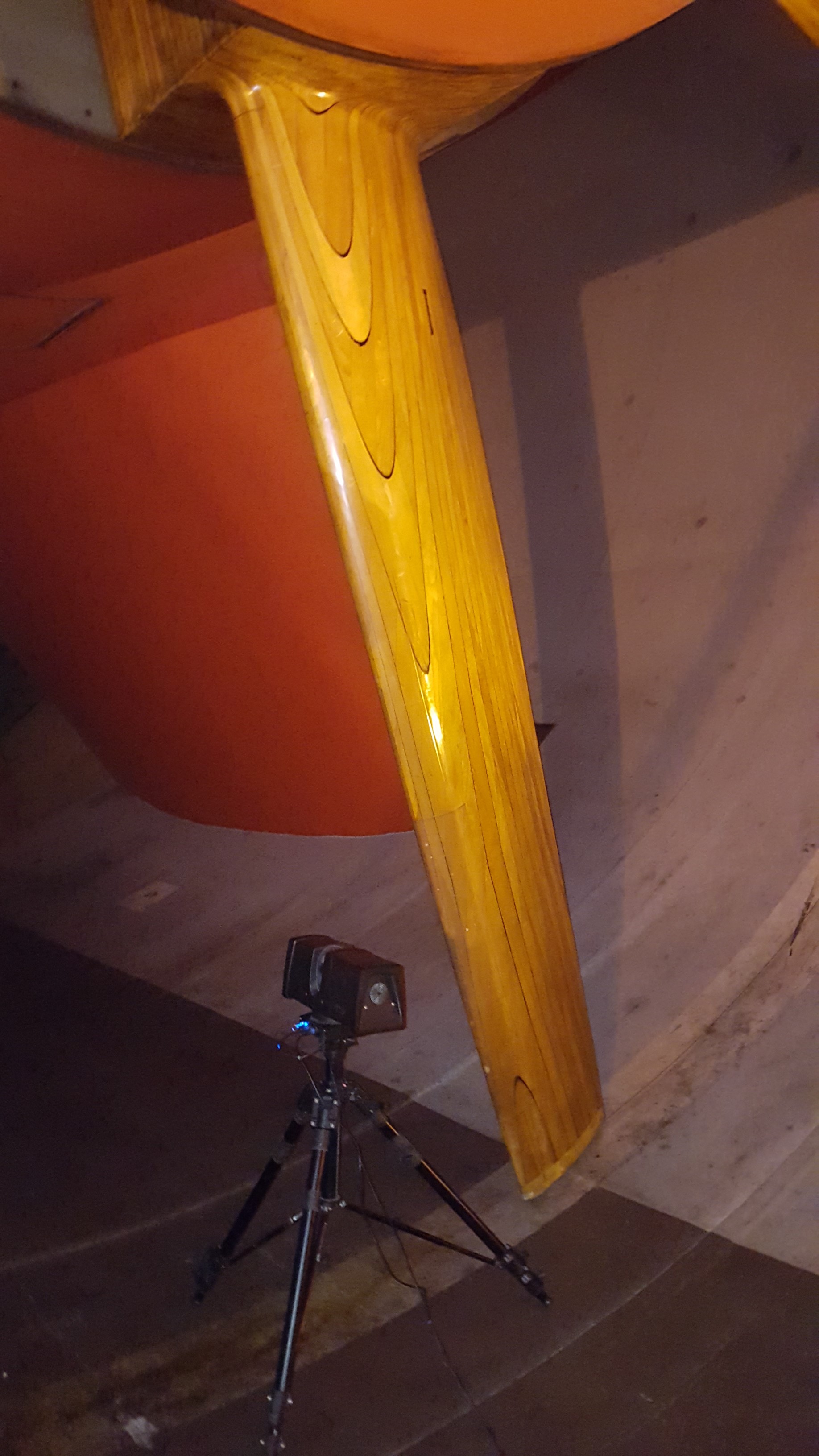
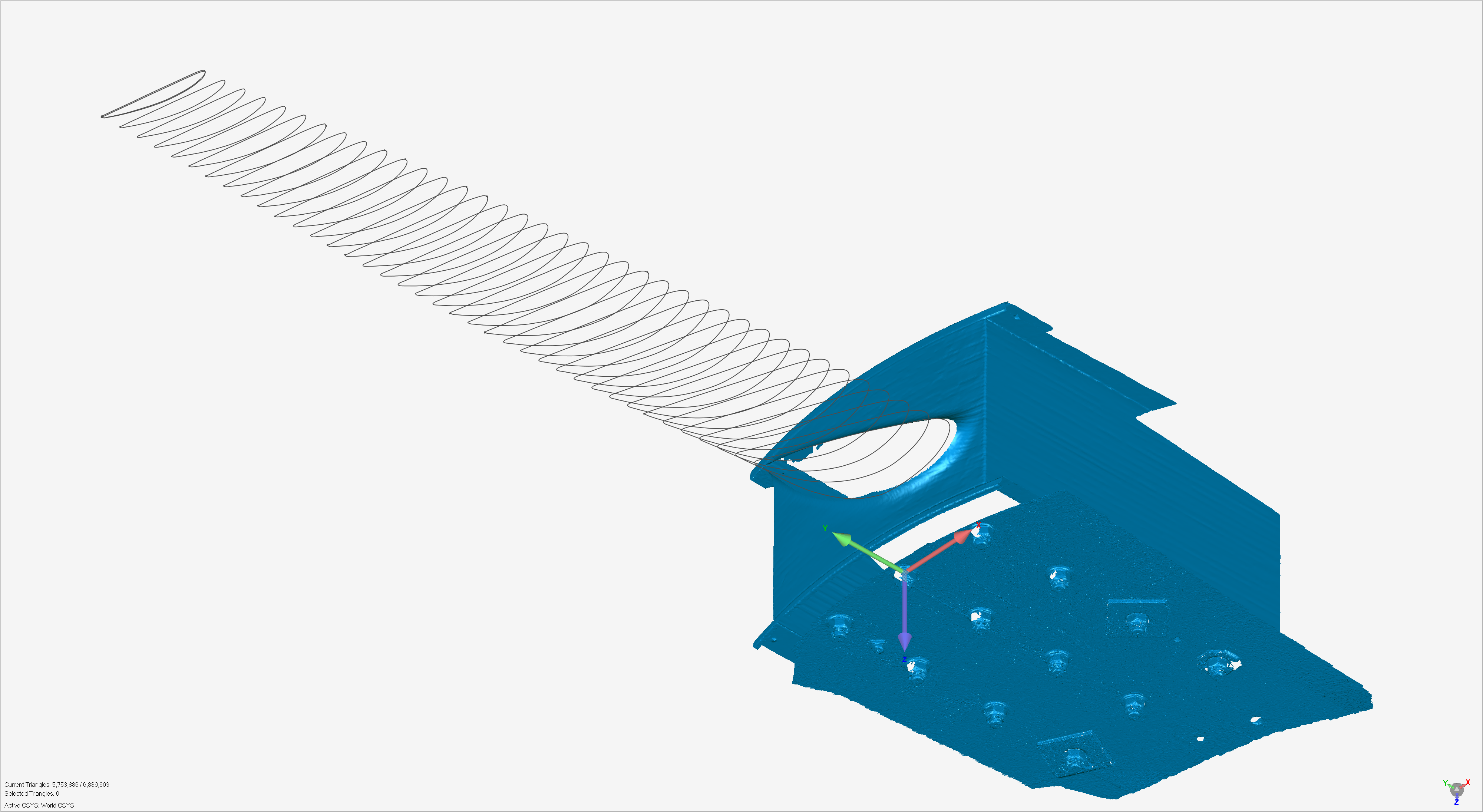
So, using our Surphaser long-range 3D laser scanner, each surface of the blade was captured all the way around. Altogether, millions of measurement points were taken over the surface of the blade thanks to the high-resolution scanning. Complete details of the wear and tear were captured during the scans.
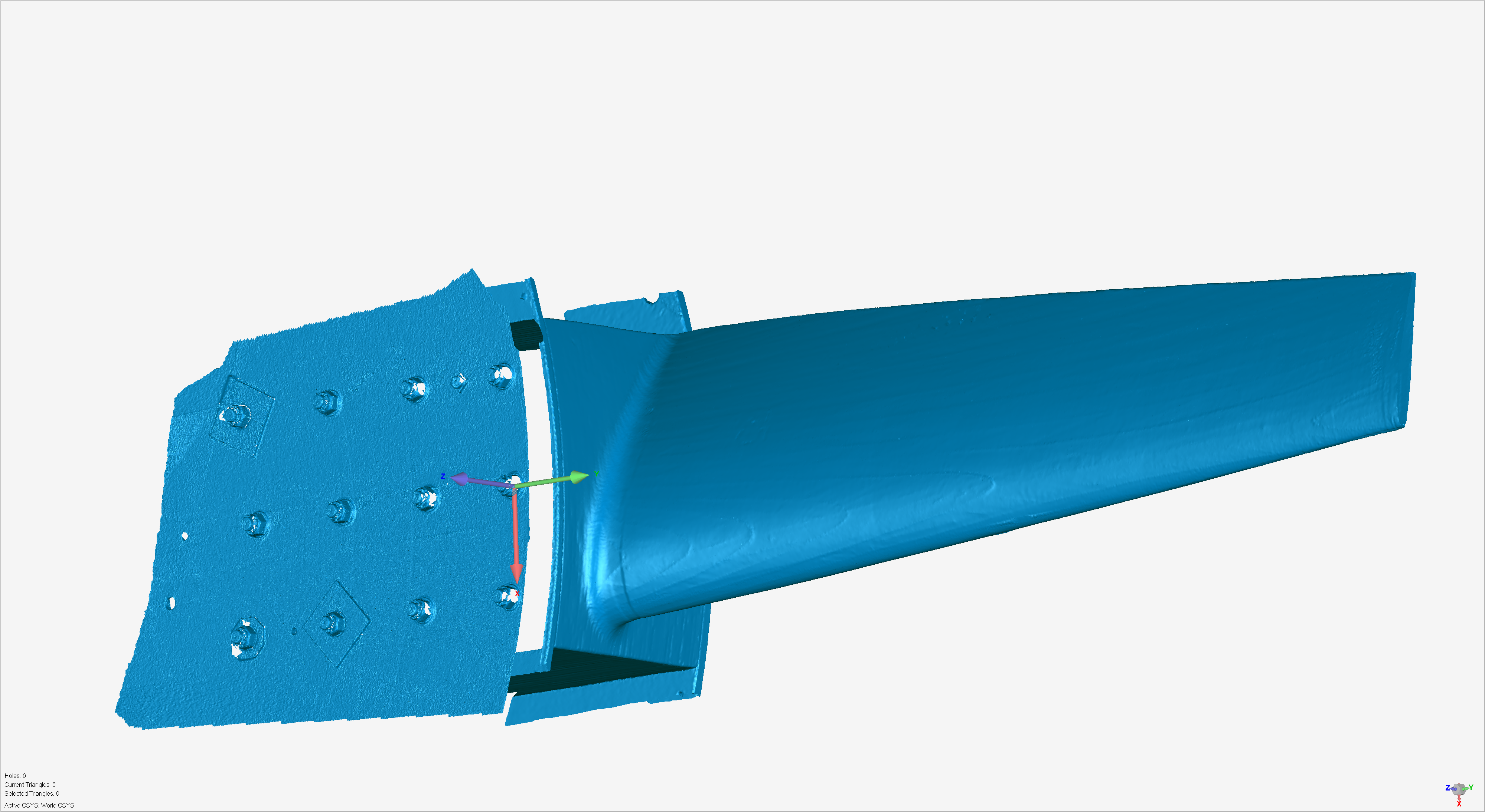
Another complication during the scanning was the hidden hub portion of the blade. Furthermore, all blades are assembled in a very tight hidden hub with 12 large bolts, with asymmetrical mounting, for foolproofing. The mounting portion of the blade needed to be scanned from up inside the center of the turbine, and then the scan data matched up to the outer blade surface data. A few hours of scanning, processing, and matching all the scans together resulted in a high-resolution polygon mesh, which was then exported to an STL file. Furthermore, an STL file is a tessellated mesh of triangles connecting the millions of measured surface points.
Reverse Engineering the Scans
The STL was then aligned to a logical coordinate system, using the mounting surfaces and features on the blade. This was done to ensure proper modeling and fitting of the blade in the assembly after the re-manufacturing.
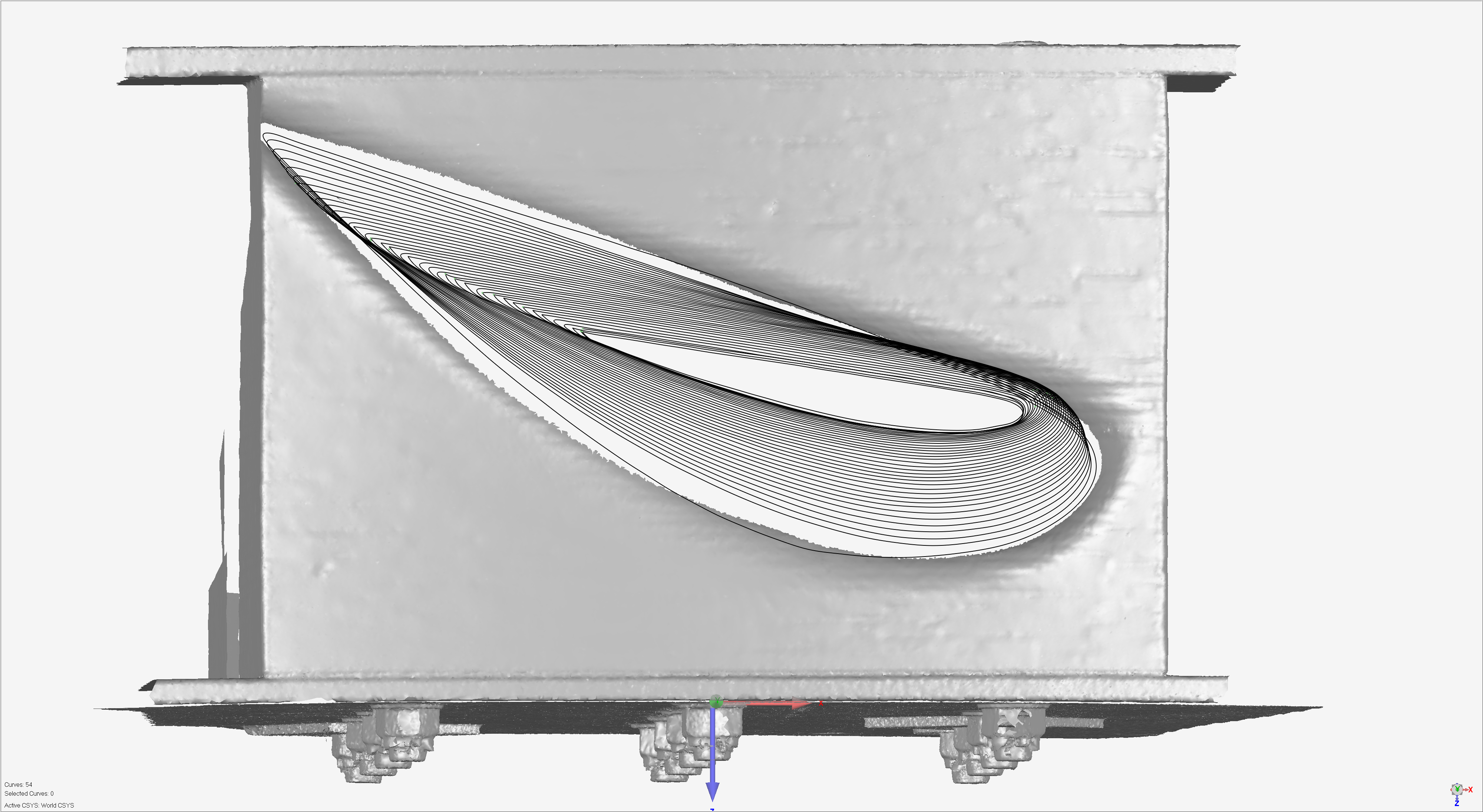
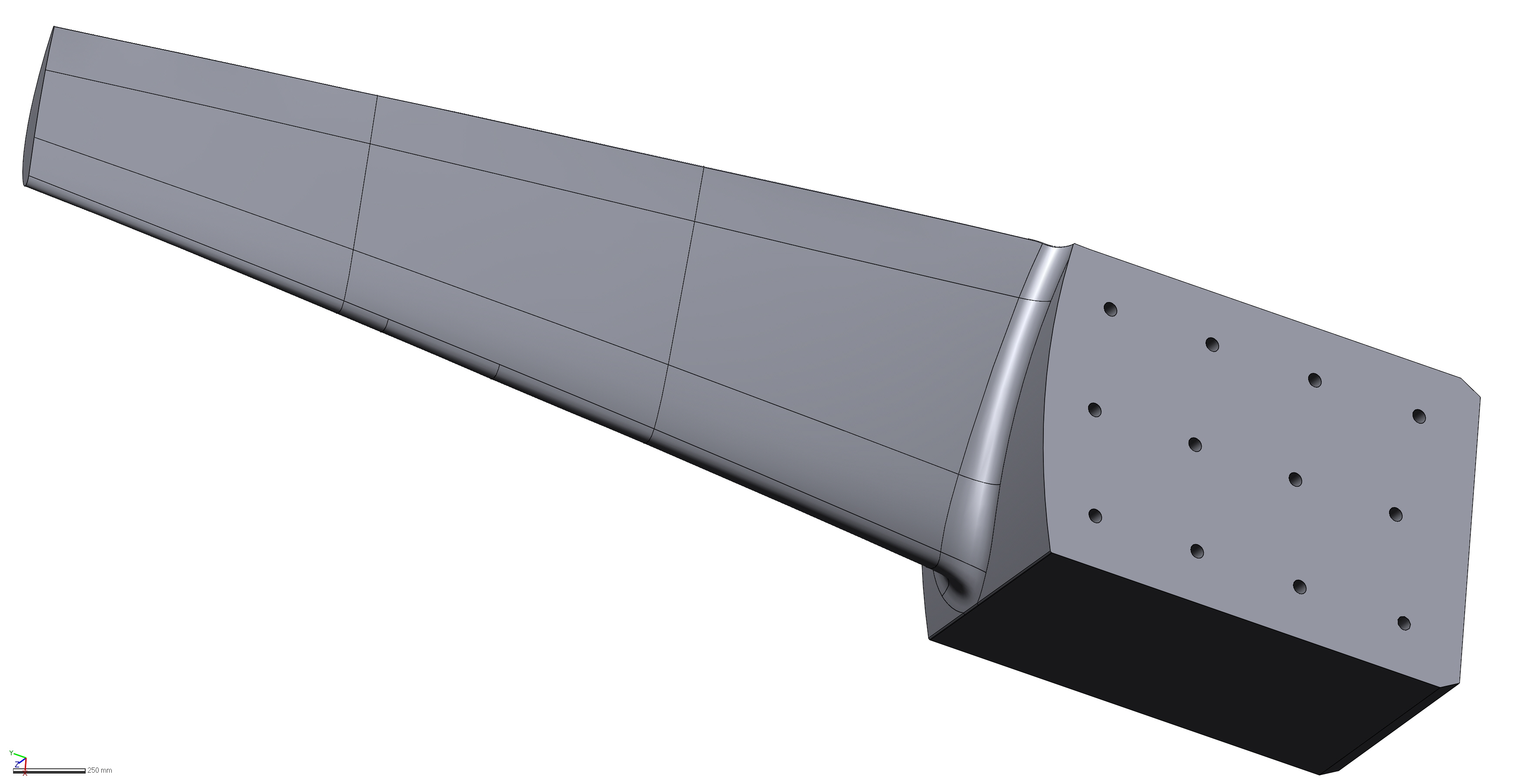
Detailed linear cross sections for the actual blade shape were created from the scan data. These cross sections were fitted with smooth spline curves, which were then split up, based on the curvature values and inflection points. Each individual feature on the surface was then made into a NURBS surface, and error-checked with the underlying STL surface, for accuracy. These individual surfaces were then trimmed, stitched, transitioned, and merged with the surrounding surfaces for a smooth and accurate water-tight solid model.
The final CAD model was then used to manufacture five new blades for the wind turbine. After all the gluing and assembly of the Spruce wood panels, the new solid model math data was used to cut the exact blade shapes on a CNC milling machine. Finally, the finishing touches included gap filling, surface polishing, and a final application of protective varnish.