
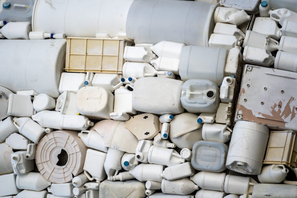
Blow molds produce some of the most common plastic items in daily life, including containers, toys, and other molded objects that need to hold a volume of air or liquid. After years of production, these tools wear, sustain impact damage, and lose the precise geometry they had when new. Reconditioning and rebuilding a blow mold traditionally meant working from worn surfaces, partial prints, or no documentation at all. 3D scanning blow molds removes that uncertainty. A high-resolution 3d scan provides a 3d model that is then used to machine new molds.
Why Blow Molds Need Reconditioning and Rebuild
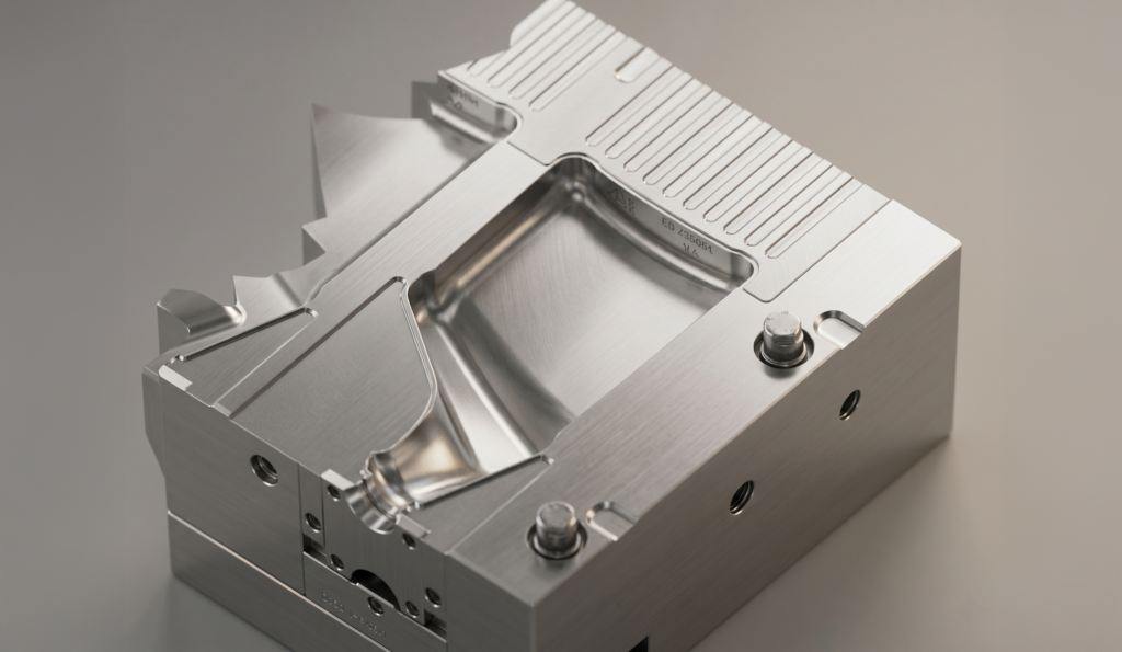
Blow molding of plastics operates on similar principles to glass blowing, but at industrial scale. A preform plastic tube is heated and inflated inside a closed mold, and the plastic takes the shape of the cavity. Any deformation or dents etc, in the mold surface will show up on the part surface.
Reconditioning blow mold repair becomes necessary for several reasons. Repeated use of the mold degrades the mold surface, as the plastic is abrasive. Scratches, dents, and corrosion create visible defects on molded parts. Design changes may require modifying an existing tool instead of cutting a new one. In many cases, the original CAD files are lost. Or, they were never created in the first place, and the molds were completely handmade with patterns or other older manufacturing methods. Older molds may also need to be duplicated for additional production . If the mold has been scanned accurately before usage and after final benching touchups, then that 3D CAD model can be used in the future to replicate the mold surface.
How 3D Scanning Supports Blow Mold Repair and Rebuilds
Blow mold reverse engineering begins with high-resolution white light , blue light or laser 3D scanning. This process measures millions of surface points very accurately across the entire mold. The resulting point cloud captures the current condition of the tool, including wear , damaged areas, and subtle changes in geometry that would be difficult to detect with other tools.
Scanning is non-contact, so there is no risk of further damaging the mold surface. Blow mold cavities often include complex and irregular shapes. It also handles complex and organic contours well. The scan data becomes the base for further CAD modeling, inspection, material removal, and additive rebuild.
The Blow Mold 3D Scanning & Reverse Engineering Workflow
A typical reverse engineering project involves the high resolution 3D digitizing/scanning of the mold surface,. Further processing of the scandata is done by converting it into STL mesh models. The STL models are then aligned in a logical coordinate system. Then in specialized reverse engineering CAD software, features are identified, surfaces are created, and then trimmed with each other. In the final stages, transitions between surfaces are built . All surfaces are then stitched together to form watertight solid models.
Step 1: Capture the Mold Surface
The mold is first 3D scanned using high-resolution white light, blue light or laser scanning equipment. The scanner projects structured light onto the surface and records how it deforms, generating a dense point cloud. Depending on the size of the tool and the production schedule, this can be done in a metrology lab or on-site with portable equipment.
Step 2: Convert 3D Scanned Point Cloud Data Into a Mesh
Raw scan data is cleaned of noise, aligned, and converted into a triangular mesh. It represents the mold exactly, including every scratch, worn edge, and mismatch between the cavity halves.
Step 3: Build a Reverse Engineered CAD Model
The mesh is then used to create a CAD model that reflects the original design intent of the mold. For reconditioning projects, wear and damage are removed in the digital model, restoring the intended geometry before any cutting tool touches the metal. The finished CAD file then becomes the master CAD for the mold
3D Scanning Inspection and Quality Control for Rebuilt Blow Molds
3D scanning is just as valuable after the repair and rebuild as it is before. Handheld 3D scanners allow molders to quickly carry out inspections and measurements of molded parts and tooling alike. Part-to-CAD comparison shows exactly where a reconditioned mold deviates from the design model. Digital metrology inspection with GD&T and SPC reporting provides tolerance checks.
This verification step is critical. A rebuilt blow mold that looks correct by eye can still produce defective containers, toys, or other parts if the cavity geometry is slightly off. Scanning removes the guesswork and gives the mold shop confidence before the tool returns to the production floor.
Rebuilding Blow Molds With CAD and Additive Manufacturing
Once a blow mold has been scanned and modeled, the repair and rebuild can take several paths. CNC machining remains the standard for many repairs. But 3d printing( metal and plastic ) has become a practical alternative for inserts, prototype tooling, and even functional production molds.
Functional Molds With SLA and DMLS
Using SLA and DMLS 3D printing, service providers can create functional molds for blow molding materials such as PET and HDPE. According to one rapid tooling source, this approach can reduce blow molding tooling costs by 90% and lead times by 70%. That makes it an attractive option for low-volume production and for validating a reconditioned mold design.
Prototype Tooling With PolyJet and FDM
PolyJet and FDM 3D printing give companies the ability to design a mold, build the tool, and blow mold near-production quality prototypes. This is useful when a reconditioned tool needs design verification before committing to full metal machining.
Rapid Mold Creation From CAD
Injection, blow, and silicone molds can be created from a 3D CAD model within a few hours using the newer 3D printers.

Real-World Results: 3D Scanning on the Blow Molding Floor
The Blowtech Group, a Scandinavian industrial concern with two plants, one in Norway and one in Sweden, specializes in plastic blow molding. Using the handheld scanners, Blowtech quickly carries out inspections and measurements of its plastic molded parts. The company reduced process time by 50% with 3D scanning.
That result speaks to the broader value of digital measurement in blow molding. When the same scanning approach is applied to reconditioning and rebuilding molds, it shortens the time between identifying a problem and returning a corrected tool to production. It also gives the mold shop a permanent digital record of the tool’s condition at every stage of the project.
Working With a 3D Scanning Service Provider
Many mold shops do not own industrial scanning equipment, and tools that are too large to ship need portable solutions. A service provider with portable on-site scanning can bring the measurement capability directly to the mold, reducing downtime and keeping the project moving.
Applications 3D, based in Metro Detroit, Michigan, has provided industrial 3D scanning, reverse engineering, inspection, CAD modeling, and 3D printing services since 2003. The company’s equipment includes blue light, white light, laser, CT scanning, portable CMMs, and many different kinds of other measurement tools. Its 3D printing capabilities include FDM, PolyJet, SLS, SLA, DMLS, and metal printing, and short run production services cover CNC machining, molding, stamping, and welding. Reverse engineering projects include blow molds, injection molds, stamping dies, organic objects, and spare parts. This combination of scanning and manufacturing services provides a single path from worn tool to verified production mold.
Frequently Asked Questions
What is the best 3D scanner for blow mold scanning?
The right scanner depends on the size, geometry, and accuracy requirements of the mold. High-resolution white light 3D scanning measures millions of surface points very accurately and is commonly used for blow mold reverse engineering. Handheld scanners such as the HandySCAN 3D from Creaform support fast on-site inspections. A scanning service provider can match the technology to the specific tool.
Can 3D printed molds be used for blow molding?
Yes. SLA and DMLS 3D printing can create functional molds for materials such as PET and HDPE, and PolyJet or FDM tooling can produce near-production quality prototype parts. According to one rapid tooling source, this approach can reduce blow molding tooling costs by 90% and lead times by 70%. A white paper provides methods and guidelines for SLA molds in the stretch blow molding process.
How long does it take to scan a blow mold?
Scan time depends on the size and complexity of the tool. Structured light 3D scanning measures millions of surface points in a single capture, so data collection is fast. Handheld scanners is more flexible, as it allows molders to carry out inspections and measurements quickly.
Why reverse engineer a blow mold before rebuilding and repairing it?
Reverse engineering creates a CAD model from an existing mold, which is essential when original drawings are lost or were never created. This digital model restores original geometry by removing wear and damage before machining begins. It also supports tool duplication, design changes, spare part production, and future replacement tooling for containers, toys, and other molded products.