
The Role of CAD Modeling and 3D Scanning in Die and Mold Manufacturing
Dies and molds are the main workhorses of manufacturing. Every stamped panel, forged bracket, and injection-molded housing traces its shape back to a tool.
However, before any tool is cut, a digital model must exist. CAD modeling for dies and molds is the process of turning an idea, a scanned part, or a old tool into a clean, machinable CAD model. From there, CAM software can easily turn the model into precise toolpaths.
When your starting point is a physical object, 3D scanning and reverse engineering help close the gap between the real world and your digital files.
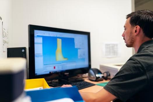

Why CAD Modeling Matters for Tooling
Applying CAD/CAM systems to tool production offers huge benefits. Specifically, it reduces lead times and improves communication between design teams and shop floors. As a result, companies see higher quality and better reproducibility. These key drivers still push tooling decisions today.
CAD/CAM systems support a wide range of metal forming processes, including:
-
- Forging
- Extrusion
- Rolling
- Sheet metal forming
Each manufacturing process places unique demands on the digital model. For example, a forging die needs robust geometry. In contrast, an injection mold must account for plastic shrinkage, cooling lines, and part ejection.
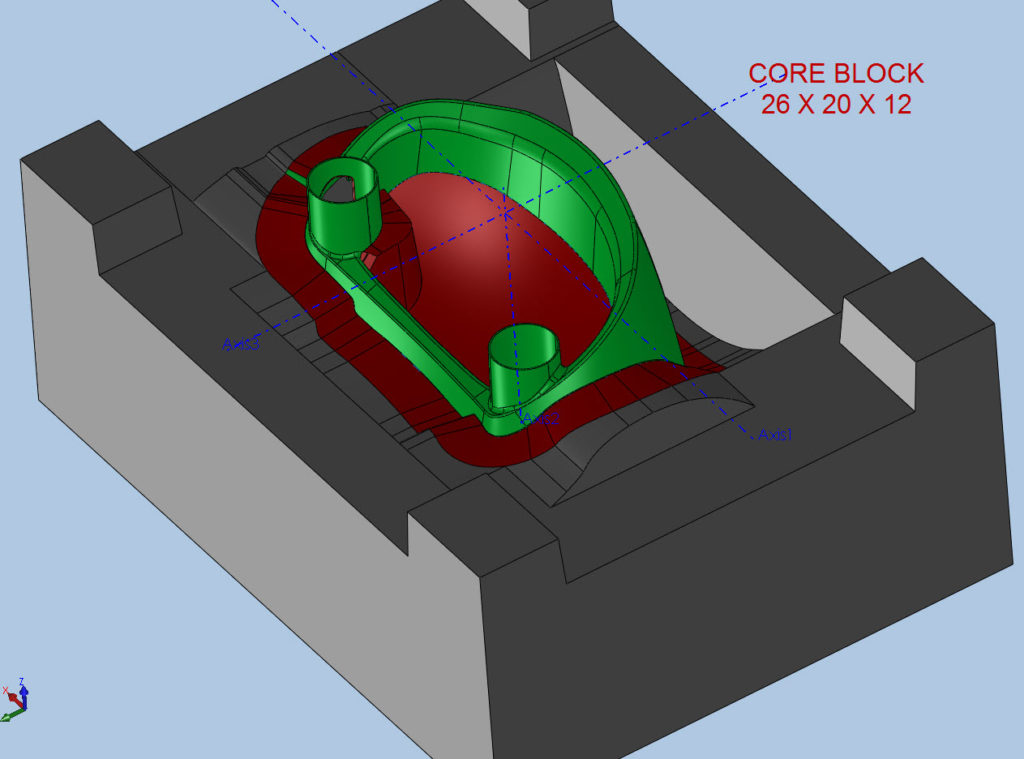
Moving From Scan Data to a Machinable Model
Many tool and die projects start without a usable CAD file. For instance, a tool may be decades old, or a part may have been sculpted by hand. Additionally, you might need a replacement part for a machine that lost its drawings long ago.
In these situations, industrial 3D scanning provides the path forward. Scan data captures exact shapes using several common tools:
-
- Blue light scanning
- Laser scanning
- CT scanning
- Portable CMMs
These tools create a dense mesh or point cloud that represents the physical surface. However, that mesh is not yet a machinable CAD model.
Preparing the Data for CAM
Creating a machinable model requires three vital steps:
-
- Clean the data: Engineers must remove noise and stray geometry.
- Fix the mesh: Software must fill open holes and resolve overlapping surfaces.
- Create surfaces: The operator fits clean surfaces to the mesh and trims them into closed volumes.
A machinable model needs continuous surfaces, closed boundaries, and clear feature definitions. Therefore, the skill of the CAD operator matters just as much as the software. Interpreting dense data requires judgment, experience, and a deep understanding of manufacturing.
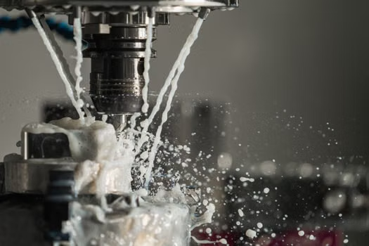
The Challenge of Organic Shapes and STL Files
Products with organic, sculpted surfaces often start as digital sculptures. Some organic software programs output STL files. Unfortunately, traditional CAD programs struggle to handle this specific mesh format.
A triangular mesh must be converted into smooth surfaces before a CNC machine can cut it reliably. Furthermore, injection molds with complex undercuts add another layer of difficulty. These undercuts require slides, lifters, or moving mechanisms that must be designed into the model before generating toolpaths.
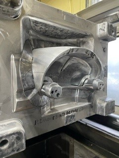
Partnering With a CAD Modeling Expert
Not every manufacturer has the in-house reverse engineering expertise to convert physical parts into CAD models. Engineering services providers fill that vital gap.
Applications 3D, based in Metro Detroit, has provided industrial 3D scanning, reverse engineering, inspection, and 3D printing services since 2003. Their advanced workflow simplifies the entire process:
[Physical Part] ➔ [3D Scan Data] ➔ [Reverse Engineering] ➔ [Clean CAD Model] ➔ [CNC Machining / 3D Printing]
First, they scan the existing tool using the best technology for its size and material. Next, they convert the scan data into a clean CAD model. Finally, they compare the model back to the scan to confirm accuracy.
The finished CAD model can then drive CNC machining, EDM, or 3D printing. It also supports inspection through part-to-CAD comparison, GD&T, and SPC reports.
Frequently Asked Questions
Can you create a machinable CAD model directly from a 3D scan?
Yes. Industrial 3D scanning captures the shape of a tool, and reverse engineering converts the mesh into a CAD model. However, an operator must clean, surface, and close the mesh into solid volumes before CAM programming.
What is the difference between a die and a mold in CAD modeling?
Dies are used in forging, extrusion, and sheet metal forming. In contrast, molds are used for plastic injection molding and die casting. The core modeling skills overlap, but the functional details differ based on the process.
Can STL files from sculpting software be machined into molds?
Yes, if your CAD/CAM software can handle mesh geometry. The best approach is to convert the STL mesh into clean surfaces before generating toolpaths.
What manufacturing processes should die and mold CAD software support?
The software must support CNC machining, EDM, and 3D printing. Additionally, wire EDM support from 2-axis to 4-axis, along with electrode programming, is valuable if your shop relies on electrical discharge machining.